
Cleanroom pressure differential is the controlled pressure difference between adjacent spaces used to establish the intended direction of leakage airflow. Positive pressure normally protects a cleaner room by moving air toward a less-clean space; negative pressure supports containment by drawing air into a hazardous room. Many projects begin with approximately 10–15 Pa between rooms of different cleanliness, but no single value is correct for every cleanroom.
A reliable pressure cascade is not created by entering a setpoint on a sensor. It depends on supply, return and exhaust airflow, envelope leakage, door and pass-box operation, room volume, control response, weather and building pressure. The URS should define the direction, target range, alarm logic, operating modes and acceptance tests for every controlled boundary.
Cleanroom Pressure Differential at a Glance
| Design questionTypical project approachImportant limitation | ||
| What does positive pressure do? | Moves leakage air from the cleaner/product-protection room toward adjacent less-clean space | Does not maintain an effective barrier through a fully open door by pressure alone |
| What does negative pressure do? | Draws air toward a containment room to reduce outward migration | Requires safe exhaust, filtration and risk assessment |
| What pressure is common? | 10–15 Pa is often used as an initial cleanroom design range | It is not a universal ISO 14644 requirement |
| What creates the pressure? | An intentional offset between supply and return/exhaust airflow acting against room leakage | A high setpoint cannot compensate for uncontrolled openings |
| What should be monitored? | Pressure across the correct room boundary, trends, alarms and operating mode | One corridor gauge may not represent the full cascade |
| What should be tested? | Static condition, door events, transfers, exhaust changes, alarms and recovery where required | A closed-door snapshot is not enough for every process |
Pressure Differential Controls Airflow Direction
Pressure is useful because air moves through cracks and openings from higher pressure toward lower pressure. When a clean production room is slightly higher than its corridor, leakage through door gaps and penetrations tends to move outward. This reduces the chance that less-clean corridor air will enter while the boundary is closed.
The pressure reading is therefore evidence of a relationship, not the contamination-control objective by itself. The objective is directional airflow across the boundary. A pressure transmitter can display the target even when another leakage path or door event creates an unexpected local flow. Design review and commissioning should consider both the measured pressure and the actual airflow path.
ISO 14644-3:2019 provides cleanroom performance test methods, including tests in as-built, at-rest and operational states. The owner should define which room state and operating modes are required for pressure verification.
Positive Pressure vs Negative Pressure Cleanrooms
Positive pressure is commonly used where product protection is the main objective, including many pharmaceutical support areas, medical device cleanrooms, laboratories, electronics assembly rooms and precision manufacturing spaces. The cleaner room is maintained at a higher pressure than the adjacent less-clean room.
Negative pressure is used where the process may harm operators, adjacent spaces or the environment. Examples can include potent powders, sensitizing materials, infectious agents or hazardous chemicals. The containment strategy may also require dedicated exhaust, terminal or safe-change filtration, airlocks and decontamination procedures.
Some projects need both objectives. A hazardous process enclosure can operate negative to its room while the cleanroom suite remains positive to the surrounding building. In more complex facilities, a pressure sink or neutral airlock can separate competing zones. The pressure schedule should show the purpose of every boundary instead of applying one direction to the whole suite.
Typical Pressure Cascade Example
A pressure cascade steps progressively between connected rooms so that leakage direction remains clear. The values below are an illustrative design basis, not a mandatory standard:
| SpaceIllustrative room pressureRelationshipControl purpose | |||
| Clean production room | +30 Pa | Highest in the example suite | Protect the main process area |
| Final gowning / personnel airlock | +20 Pa | 10 Pa below production | Support staged entry without reversing the cascade |
| Clean corridor | +10 Pa | 10 Pa below gowning | Buffer the suite from uncontrolled areas |
| Uncontrolled surrounding space | 0 Pa reference | 10 Pa below corridor | Reference condition for the example |
The absolute numbers are less important than the boundary relationships and their stability. The design team should check whether adjacent rooms can maintain the intended steps simultaneously. If one room depends on several doors, shared returns or variable process exhaust, changing one airflow can affect the entire cascade.
For class-specific context, our ISO 7 cleanroom guide explains why 10–15 Pa is commonly used as a starting point but is not prescribed universally by ISO 14644-1.
How HVAC Airflow Creates Room Pressure
Room pressure is produced by an airflow offset. In a positive room, supply air exceeds the controlled return and exhaust airflow, and the excess leaves through designed or unavoidable leakage paths. In a negative room, exhaust and return exceed supply, so makeup air enters through the boundary.
A simplified balance is:
Offset airflow = supply airflow − return airflow − exhaust airflow
This relationship is useful for balancing, but the resulting pressure also depends on leakage area and resistance. A tightly sealed room may need a smaller offset to achieve the target pressure, while a leaky envelope can consume substantial airflow and still remain unstable. Excessively sealing a room without considering door force, relief paths or control response can create other operating problems.
The air-balance design should include process exhaust, fume hoods, biosafety cabinets, door undercuts, transfer openings, duct leakage and operating modes. Variable exhaust or equipment startup can shift the balance faster than a slowly responding supply control can correct it.
Doors, Airlocks and Pass Boxes
Opening a door greatly increases the leakage area and collapses the static pressure difference across that boundary. Pressure alone should not be described as preventing contamination through an open doorway. Protection during door events depends on door-opening duration, airflow direction, airlock arrangement, movement, recovery and operating discipline.
Personnel and material airlocks reduce direct connection between incompatible spaces. Interlocks can prevent both doors from being opened at once, but the sequence must include emergency release, fire-safety requirements, transfer capacity and a practical cycle time. If operators routinely wait too long or cannot move the required carts, workarounds will defeat the design.
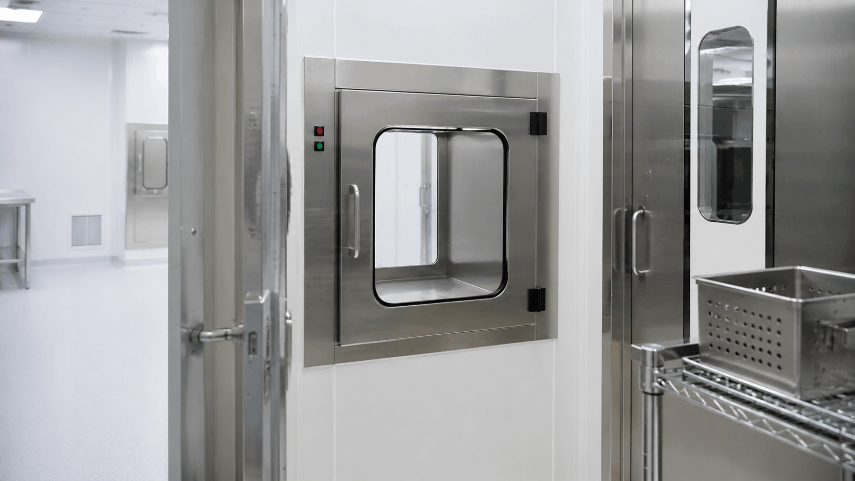
Pass boxes and transfer hatches also change the pressure relationship. Their seals, interlock, chamber purge or airflow, load size, cleaning method and opening frequency should be included in the room-balance calculation. A poorly sealed hatch can become a permanent bypass path.
Design for Door Events and Recovery
A static acceptance reading with every door closed is necessary but may not be sufficient. The qualification plan should identify representative events: personnel entry, material transfer, simultaneous exhaust operation, process equipment startup and transition between occupied and setback modes.
For each important event, define what constitutes acceptable behavior. The pressure may briefly fall below its normal band when a door opens; the system should restore the required relationship after closure within a project-defined recovery time. Alarm delays should distinguish expected short events from failures without hiding persistent loss of control.
Smoke visualization can help show the actual direction of airflow at doors, hatches and process interfaces. Pressure trending can show how long disturbances last and whether one event destabilizes adjacent rooms. These observations are especially useful when a cleanroom passes static balancing but experiences recurring operational alarms.
Pressure Monitoring and Sensor Placement
A differential pressure sensor compares two specific spaces. The high and low pressure references must correspond to the boundary being controlled. Tubing should be protected from blockage, kinking, condensation and accidental disconnection, and the room-side ports should not be placed where direct supply jets or local turbulence distort the reading.
Critical relationships may require a local display, building-management or environmental-monitoring connection, data logging and alarm notification. The specification should define measurement range, accuracy, calibration, display units, trend interval, alert and action limits, delay, reset behavior and response responsibility.
Sensor zero drift can be significant when the room target is only a few pascals. Calibration and zero checks should follow the quality system and manufacturer guidance. A stable displayed value should also be compared with an independent calibrated instrument during qualification and periodic verification.
Pressure Control Strategies
Different facilities use different control approaches:
- Fixed airflow balance: supply, return and exhaust are balanced to create a stable offset. This can be simple and reliable where operating conditions change little.
- Airflow tracking: controls maintain a defined supply-to-exhaust offset as variable process exhaust changes.
- Direct pressure control: a pressure signal modulates a damper, fan or airflow setpoint. Tuning is important to prevent hunting between connected rooms.
- Hybrid control: airflow tracking provides the main balance while pressure acts as a trim or supervisory signal.
Directly controlling every room against its neighbor can create unstable loops if each controller reacts to the same disturbance. A suite-level control narrative should identify the reference space, primary controlled variables, response priority, minimum airflow and failure mode.
Commissioning and Acceptance Test Matrix
| Test conditionWhat to verifyEvidence | ||
| Normal closed-door operation | Target, tolerance and direction at every scheduled boundary | Calibrated readings and room schedule |
| Door opening and closure | Expected dip, airflow direction and recovery behavior | Trend data and observation or visualization |
| Material transfer / pass box cycle | No unintended reversal across critical boundaries | Cycle test and pressure trend |
| Maximum process exhaust | Containment and adjacent-room cascade remain acceptable | Airflow and pressure readings |
| Alarm challenge | Setpoint, delay, notification, acknowledgement and response | Alarm test record |
| Power or fan failure | Safe failure state and restart sequence | Control-sequence test |
| Occupied operation | Normal people, equipment and transfers do not cause persistent loss of control | Operational qualification or monitoring trend |
Troubleshooting Unstable Cleanroom Pressure
| Observed problemPossible causesChecks | ||
| Pressure is always low | Insufficient supply offset, excessive exhaust, open leakage path or blocked supply | Air-balance readings, door seals, penetrations, filters and dampers |
| Pressure changes when another room door opens | Shared return path, weak cascade, common control loop or inadequate airlock separation | Suite trend test and door sequence |
| Reading oscillates | Controller hunting, turbulent pressure port, oversized damper or poor sensor damping | Control tuning, port location and signal trend |
| Gauge and airflow direction disagree | Wrong reference tubing, local jet influence, another leakage path or sensor zero error | Tubing trace, independent instrument and smoke visualization |
| Frequent nuisance alarms | Limits too tight, delay too short, door behavior or slow recovery | Event trends, risk-based limits and operator workflow |
| Pressure fails after filter loading | Fan reserve is inadequate or controls do not compensate for rising resistance | Filter pressure drop, airflow volume and fan operating point |
Cleanroom Pressure Differential URS Checklist
- Identify the product-protection or containment objective for every room.
- Provide a room-by-room pressure cascade with the reference space.
- Define normal target, acceptable band and airflow direction.
- List normal, setback, cleaning, process-exhaust and failure modes.
- Define door, airlock and pass-box operating assumptions.
- State monitoring, calibration, trending and alarm requirements.
- Specify static and operational acceptance tests plus recovery criteria where needed.
- Assign responsibility for balancing, controls, validation and final documentation.
For GMP cleanroom projects, connect the pressure schedule to the contamination control strategy, personnel and material routes, process exhaust, monitoring plan and change-control system. Pressure should support the risk logic of the facility, not exist as a separate HVAC target.
Hurricane Techs Recommendation
Define pressure relationships during layout and HVAC design, then test them under realistic operating conditions. Avoid approving a proposal that gives one pressure value without a room schedule, airflow basis, door assumptions, control sequence, alarms and acceptance method.
Hurricane Techs provides cleanroom HVAC integration, pass box solutions, design consulting and validation support. For a pressure-control review, provide the room layout, classifications, hazards, occupancy, exhaust schedule, door and transfer sequence, target operating modes and monitoring requirements.
FAQ
What pressure differential is common in cleanrooms?
Many projects use 10–15 Pa between rooms of different cleanliness as an initial design range. The final value should be justified for the process, leakage, door arrangement, containment risk and governing requirements.
Does ISO 14644 require a specific room pressure?
ISO 14644-1 classification does not prescribe one universal pressure value for each ISO class. The project should define pressure according to contamination-control objectives and verify it using the agreed test method.
Why does cleanroom pressure drop when a door opens?
An open door greatly increases the flow area between rooms, reducing the static pressure difference. Airlock design, opening time, airflow offset and HVAC recovery determine what happens after the door closes.
Can pressure alone prevent contamination through an open door?
No. Protection during an open-door event depends on directional airflow, door duration, airlocks, movement and recovery. The closed-door pressure value alone is not sufficient evidence.
Should a hazardous cleanroom be negative pressure?
Hazardous or potent processes often require negative pressure or local containment, but product protection, operator safety and environmental risk must be assessed together. The final strategy may combine room pressure with enclosures and dedicated exhaust.
Where should a differential pressure sensor be installed?
It should compare the correct pair of spaces using protected pressure ports located away from direct supply jets and local turbulence. Placement, range, accuracy and calibration should be documented.


